Synchronized motion
Position feedback and proportional valve control coordinate the two cylinders.
SNSIE / SPC
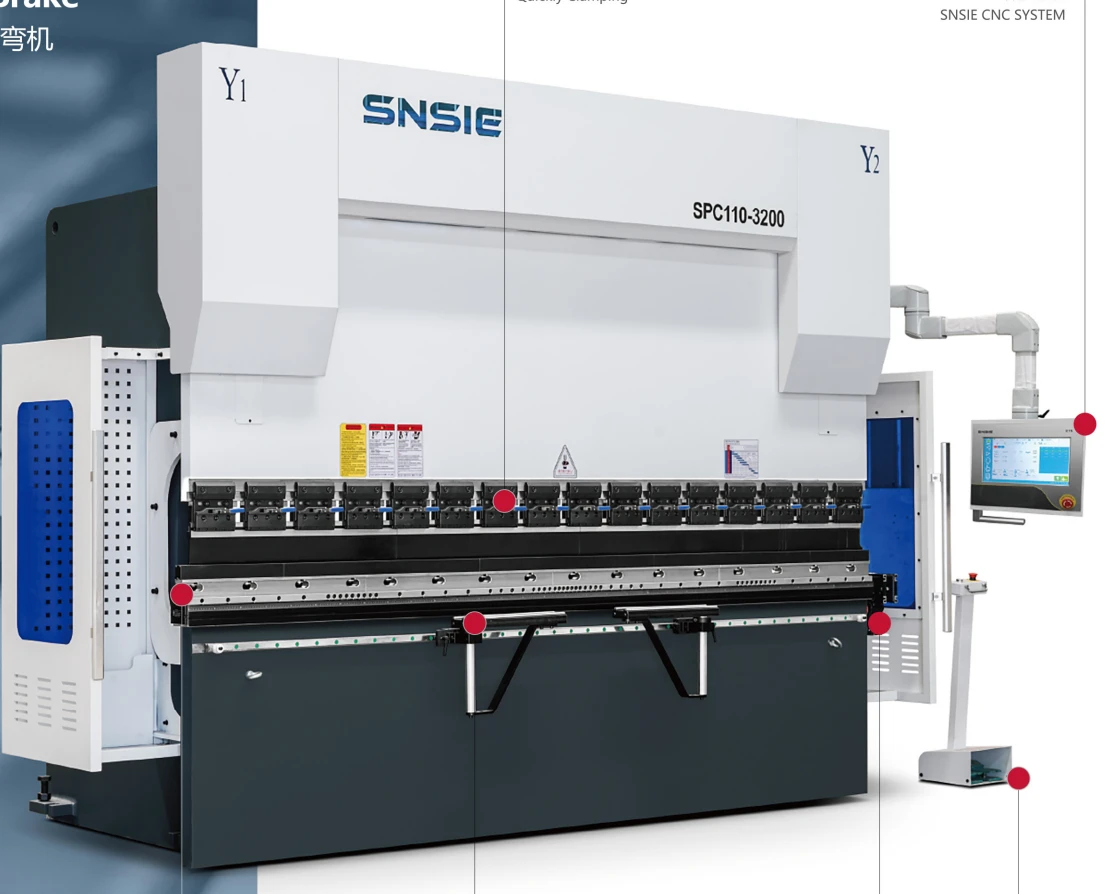
Electro-Hydraulic Synchronized CNC Press Brake
CNC BENDING / SPC
An electro-hydraulic synchronized platform with closed-loop positioning and mechanical crowning.
01 / DRIVE TECHNOLOGY
The SPC platform coordinates the two cylinders through the CNC system, position feedback and proportional hydraulic valve control. Feedback from the two sides is used to control ram position and synchronized motion.
The catalogue lists a standard 4+1-axis arrangement: Y1 and Y2 for the ram, X and R for backgauge positioning, and V for compensation. Mechanical crowning and throat-deformation compensation address different sources of deflection during bending.
SPC catalogue / pp. 05-06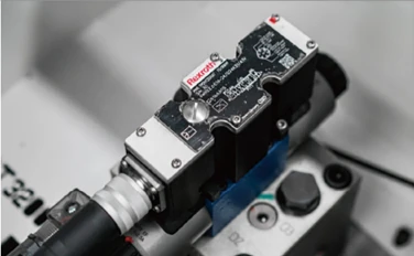
Position feedback and proportional valve control coordinate the two cylinders.
The catalogue lists Y1, Y2, X, R and V control for the standard configuration.
Mechanical crowning and throat compensation support bending consistency.
Consider SPC when comparing an electro-hydraulic synchronized platform with the servo-driven series. Hydraulic component suppliers and the final axis configuration must be specified in the machine quotation.
02 / MACHINE CONFIGURATION
Frame strength, sheet positioning, tooling and compensation work together. The following assemblies appear in the shared SPES / SPS / SPC standard-configuration section of the 2024 catalogue.
Catalogue standard
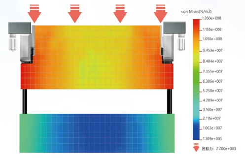
The catalogue describes a strengthened frame and a thickened, widened ram to limit deformation under bending load. The frame provides the structural base for the tooling and positioning systems.
Catalogue standard
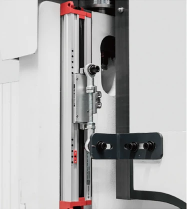
A displacement sensor measures small deformation at the machine throat. This feedback supports compensation during bending rather than relying only on the unloaded frame position.
Catalogue standard
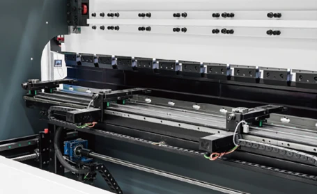
Ball-screw transmission and linear guides position the sheet against the stop fingers. The crossbeam uses a double-guide arrangement, while multi-level fingers provide different contact positions for the workpiece.
Catalogue standard
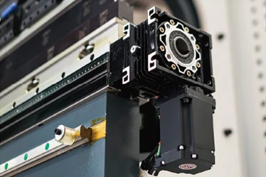
The compensation setting is calculated and controlled through the CNC system. Mechanical crowning adjusts the worktable to help maintain a consistent bending angle along the working length.
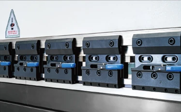
Catalogue standard
The upper-tool quick-clamp arrangement is intended to make installation and removal more convenient. It supports tool retention and positioning during setup without making hydraulic WILA clamping part of the base package.
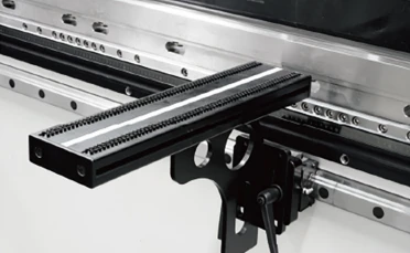
Catalogue standard
Front supports move along a linear guide and can be positioned for the workpiece. Rotation and height adjustment assist sheet support during setup and handling.
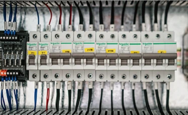
Catalogue standard
The catalogue identifies Schneider electrical components and graphite self-lubricating copper plates. The plates provide a low-friction wear surface, while the electrical cabinet brings machine control components together.
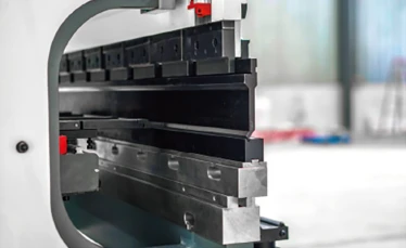
Catalogue standard
Forged and quenched press brake tooling is described alongside the lower-tool interface. The catalogue lists a double-V / T quick-change lower clamp as standard, with other holder arrangements available for discussion.
Catalogue standard equipment is a reference for the published range. Exact components, suppliers and the machine-specific supply list are confirmed in the quotation. The drive and hydraulic architecture remain series-specific.
03 / CNC CONTROL
The SPC machine illustration shows an SNSIE CNC system and lists 4+1-axis control. A controller's maximum capability does not mean every supported axis is installed on the machine.
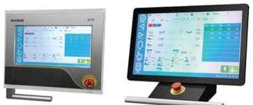
Shown on SPC: SNSIE system
A one-page programming interface brings bending information together, with programmable bend speed and step settings.
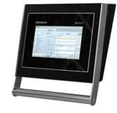
Configuration choice
The catalogue spans numerical touch operation, 2D graphical programming and 3D simulation across different Delem controllers.
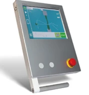
Configuration choice
CybTouch and VT interfaces provide bending-program and calculation functions with graphical operation options suited to different requirements.
Controller features differ by model and software version. Axis count, graphical functions and machine interfaces must match the selected equipment; listing a controller family does not establish compatibility with every machine or option.
04 / OPTIONS & AUTOMATION
Additional positioning, measurement, clamping and handling equipment can be discussed as part of your machine configuration. These items are separate from the catalogue standard assemblies above.
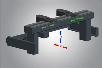
Optional equipment
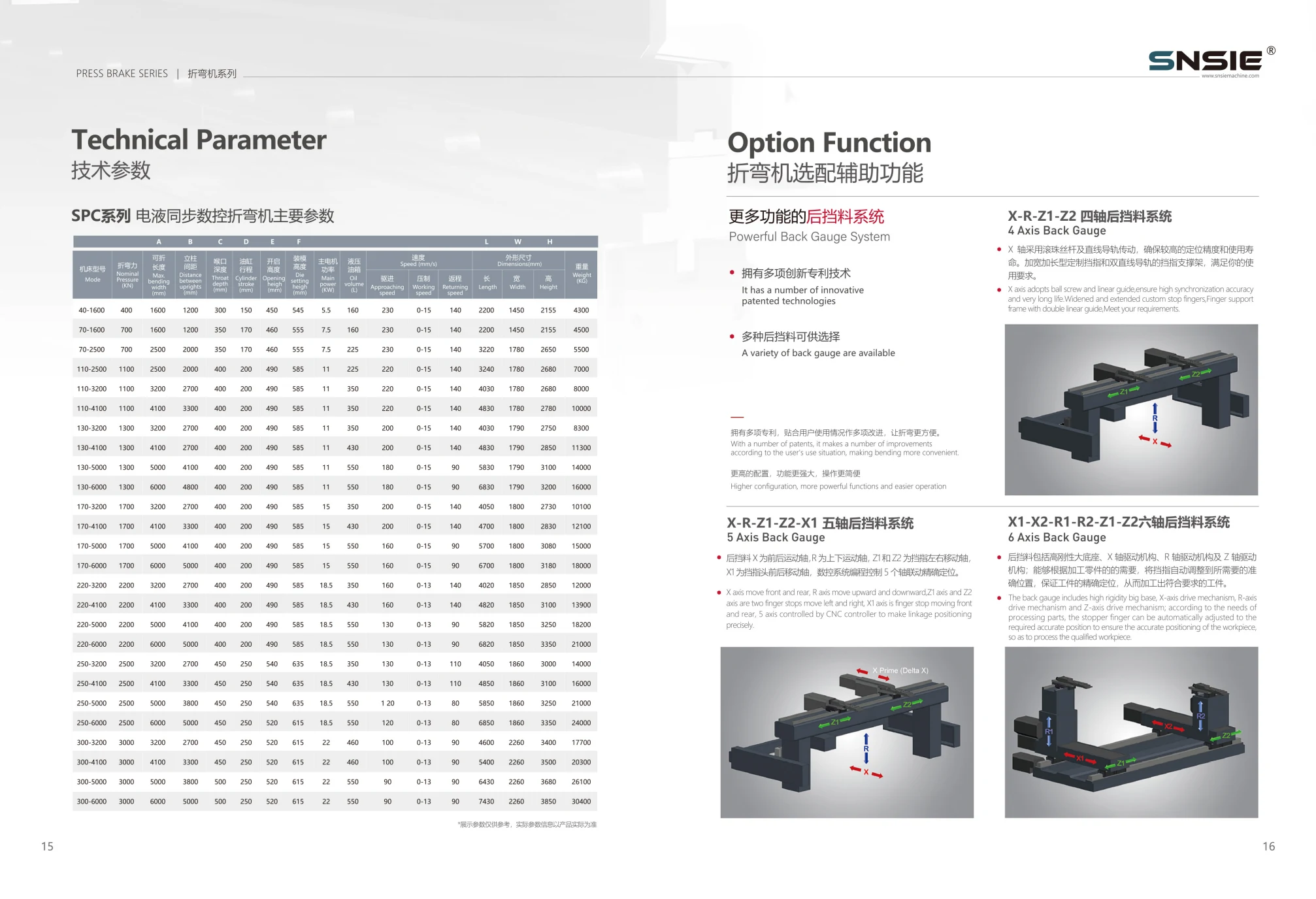
Additional independently positioned fingers and axes support more involved workpiece positioning. These are backgauge-axis counts, not a count of all machine axes.
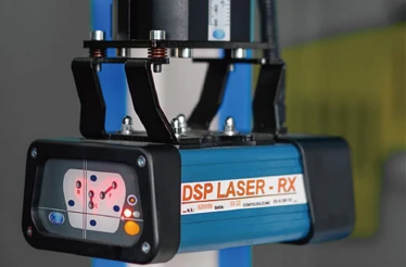
Optional equipment
The catalogue illustrates a DSP laser protection device at the tooling area. The machine's complete safeguarding arrangement must be specified for the equipment and destination requirements.
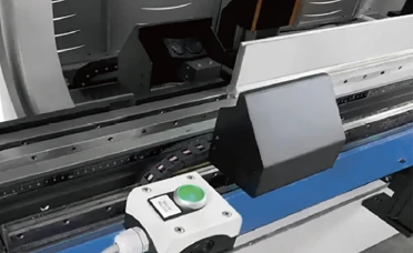
Optional equipment
Laser angle measurement provides information about the workpiece bend angle. It is a process-measurement option and serves a different purpose from the laser safety device.
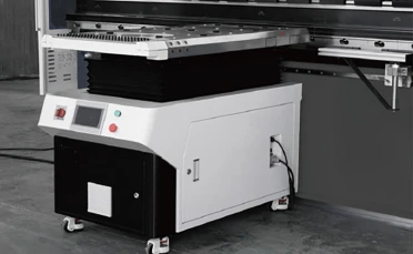
Optional equipment
Unlike manually positioned front supports, a follower support tracks the workpiece as it turns during a bend. The CNC system calculates and controls the following angle and speed.
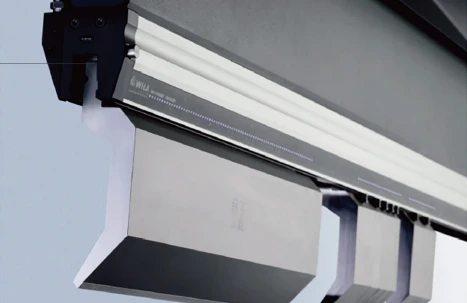
Optional equipment
The WILA upper-tool system uses hydraulic clamping with electrically controlled clamping and release. It is a tooling-interface option for tool changes, not the same assembly as the catalogue quick clamp.
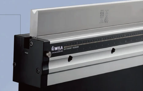
Optional equipment
The illustrated lower-tool holder uses hydraulic clamping with electrically controlled release. Its suitability depends on the selected die interface and machine configuration.
Application-specific
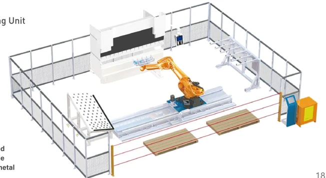
The catalogue shows a flexible bending cell combining the press brake, robot and workpiece-handling areas. The layout is a reference concept, not a fixed package or a documented customer installation.
Share your material, thickness, maximum bend length, drawings and production sequence to discuss a compatible machine package.
CONFIGURATION QUESTIONS
The SPC machine illustration shows an SNSIE CNC system and lists 4+1-axis control. A controller's maximum capability does not mean every supported axis is installed on the machine. The supplied controller is recorded in the machine quotation.
No. The standard assemblies follow the catalogue section on printed pages 07-10. Multi-axis backgauges, auxiliary measurement, hydraulic WILA holders and automation are described separately on pages 16-18. Final availability and compatibility depend on the machine configuration.
No. Backgauge packages count the positioning axes in that assembly. Machine-axis descriptions also include ram and compensation control. For example, the SPC catalogue lists Y1, Y2, X, R and V as 4+1-axis control.
Provide the part drawing, material and thickness, bend lengths, required geometry and production sequence. These guide discussion of punch and die profiles, backgauge access and sheet support. The catalogue tool-installation diagrams are available in the technical resources.
Tool installation referenceTECHNICAL PARAMETERS
| Model | Nominal pressure (kN) | Bending length (mm) | Upright distance (mm) | Throat depth (mm) | Cylinder stroke (mm) | Opening height (mm) | Die setting height (mm) | Main motor power (kW) | Oil tank volume (L) | Approaching speed (mm/s) | Working speed (mm/s) | Returning speed (mm/s) | Machine length (mm) | Machine width (mm) | Machine height (mm) | Weight (kg) | Inquiry |
|---|---|---|---|---|---|---|---|---|---|---|---|---|---|---|---|---|---|
| SPC40-1600 | 400 | 1,600 | 1,200 | 300 | 150 | 450 | 545 | 5.5 | 160 | 230 | 0-15 | 140 | 2,200 | 1,450 | 2,155 | 4,300 | Inquire |
| SPC70-1600 | 700 | 1,600 | 1,200 | 350 | 170 | 460 | 555 | 7.5 | 160 | 230 | 0-15 | 140 | 2,200 | 1,450 | 2,155 | 4,500 | Inquire |
| SPC70-2500 | 700 | 2,500 | 2,000 | 350 | 170 | 460 | 555 | 7.5 | 225 | 230 | 0-15 | 140 | 3,220 | 1,780 | 2,650 | 5,500 | Inquire |
| SPC110-2500 | 1,100 | 2,500 | 2,000 | 400 | 200 | 490 | 585 | 11 | 225 | 220 | 0-15 | 140 | 3,240 | 1,780 | 2,680 | 7,000 | Inquire |
| SPC110-3200 | 1,100 | 3,200 | 2,700 | 400 | 200 | 490 | 585 | 11 | 350 | 220 | 0-15 | 140 | 4,030 | 1,780 | 2,680 | 8,000 | Inquire |
| SPC110-4100 | 1,100 | 4,100 | 3,300 | 400 | 200 | 490 | 585 | 11 | 350 | 220 | 0-15 | 140 | 4,830 | 1,780 | 2,780 | 10,000 | Inquire |
| SPC130-3200 | 1,300 | 3,200 | 2,700 | 400 | 200 | 490 | 585 | 11 | 350 | 200 | 0-15 | 140 | 4,030 | 1,790 | 2,750 | 8,300 | Inquire |
| SPC130-4100 | 1,300 | 4,100 | 2,700 | 400 | 200 | 490 | 585 | 11 | 430 | 200 | 0-15 | 140 | 4,830 | 1,790 | 2,850 | 11,300 | Inquire |
| SPC130-5000 | 1,300 | 5,000 | 4,100 | 400 | 200 | 490 | 585 | 11 | 550 | 180 | 0-15 | 90 | 5,830 | 1,790 | 3,100 | 14,000 | Inquire |
| SPC130-6000 | 1,300 | 6,000 | 4,800 | 400 | 200 | 490 | 585 | 11 | 550 | 180 | 0-15 | 90 | 6,830 | 1,790 | 3,200 | 16,000 | Inquire |
| SPC170-3200 | 1,700 | 3,200 | 2,700 | 400 | 200 | 490 | 585 | 15 | 350 | 200 | 0-15 | 140 | 4,050 | 1,800 | 2,730 | 10,100 | Inquire |
| SPC170-4100 | 1,700 | 4,100 | 3,400 | 400 | 200 | 490 | 585 | 15 | 430 | 200 | 0-15 | 140 | 4,700 | 1,800 | 2,830 | 12,100 | Inquire |
| SPC170-5000 | 1,700 | 5,000 | 4,100 | 400 | 200 | 490 | 585 | 15 | 550 | 160 | 0-15 | 90 | 5,700 | 1,800 | 3,080 | 15,000 | Inquire |
| SPC170-6000 | 1,700 | 6,000 | 5,000 | 400 | 200 | 490 | 585 | 15 | 550 | 160 | 0-15 | 90 | 6,700 | 1,800 | 3,180 | 18,000 | Inquire |
| SPC220-3200 | 2,200 | 3,200 | 2,700 | 400 | 200 | 490 | 585 | 18.5 | 350 | 160 | 0-13 | 140 | 4,020 | 1,850 | 2,850 | 12,000 | Inquire |
| SPC220-4100 | 2,200 | 4,100 | 3,300 | 400 | 200 | 490 | 585 | 18.5 | 430 | 160 | 0-13 | 140 | 4,820 | 1,850 | 3,100 | 13,900 | Inquire |
| SPC220-5000 | 2,200 | 5,000 | 4,100 | 400 | 200 | 490 | 585 | 18.5 | 550 | 130 | 0-13 | 90 | 5,820 | 1,850 | 3,250 | 18,200 | Inquire |
| SPC220-6000 | 2,200 | 6,000 | 5,000 | 400 | 200 | 490 | 585 | 18.5 | 550 | 130 | 0-13 | 90 | 6,820 | 1,850 | 3,350 | 21,000 | Inquire |
| SPC250-3200 | 2,500 | 3,200 | 2,700 | 450 | 250 | 540 | 635 | 18.5 | 350 | 130 | 0-13 | 110 | 4,050 | 1,860 | 3,000 | 14,000 | Inquire |
| SPC250-4100 | 2,500 | 4,100 | 3,300 | 450 | 250 | 540 | 635 | 18.5 | 430 | 130 | 0-13 | 110 | 4,850 | 1,860 | 3,100 | 16,000 | Inquire |
| SPC250-5000 | 2,500 | 5,000 | 3,800 | 450 | 250 | 540 | 635 | 18.5 | 550 | 120 | 0-13 | 80 | 5,850 | 1,860 | 3,250 | 21,000 | Inquire |
| SPC250-6000 | 2,500 | 6,000 | 5,000 | 450 | 250 | 520 | 615 | 18.5 | 550 | 120 | 0-13 | 80 | 6,850 | 1,860 | 3,350 | 24,000 | Inquire |
| SPC300-3200 | 3,000 | 3,200 | 2,700 | 450 | 250 | 520 | 615 | 22 | 460 | 100 | 0-13 | 90 | 4,600 | 2,260 | 3,400 | 17,700 | Inquire |
| SPC300-4100 | 3,000 | 4,100 | 3,300 | 450 | 250 | 520 | 615 | 22 | 460 | 100 | 0-13 | 90 | 5,400 | 2,260 | 3,500 | 20,300 | Inquire |
| SPC300-5000 | 3,000 | 5,000 | 3,800 | 500 | 250 | 520 | 615 | 22 | 550 | 90 | 0-13 | 90 | 6,430 | 2,260 | 3,680 | 26,100 | Inquire |
| SPC300-6000 | 3,000 | 6,000 | 5,000 | 500 | 250 | 520 | 615 | 22 | 550 | 90 | 0-13 | 90 | 7,430 | 2,260 | 3,850 | 30,400 | Inquire |
All 26 SPC models from the 2024 catalogue, PDF page 10 (printed page 15). Pressure is listed in kN. These values are catalogue references; final specifications are confirmed in the machine quotation.
SPES SERIES
A dual-servo oil-electric hybrid drive for controlled, on-demand sheet-metal bending.
Explore SPESSPS SERIES
A main-servo-motor platform combining a single servo pump with CNC bending control.
Explore SPSYOUR NEXT BENDING PROJECT