
Three drive platforms. One focus: your next bend.
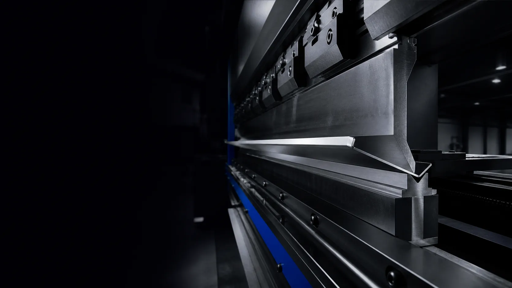
Make every bend count.
Delem DA-69S | Delem DA-66S | ESA S875
400–3,000 kN | 1,600–6,000 mm
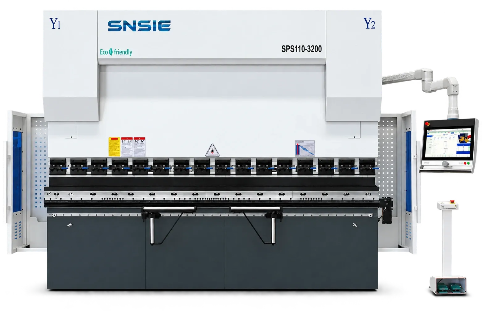
Choose the drive architecture that fits your production. UltraBend brings together the three press brake series in the SNSIE catalogue.
The SPES platform uses a separate servo motor and servo pump for each cylinder. The two sides of the ram work together under CNC control, combining hydraulic forming force with on-demand motor operation.
Explore SPES specificationsThe SPS series uses a main servo motor with a single servo-pump drive. Rather than running continuously at the same demand, the pump operates according to the machine's bending cycle.
Explore SPS specificationsThe SPC platform coordinates the two cylinders through the CNC system, position feedback and proportional hydraulic valve control. Feedback from the two sides is used to control ram position and synchronized motion.
Explore SPC specifications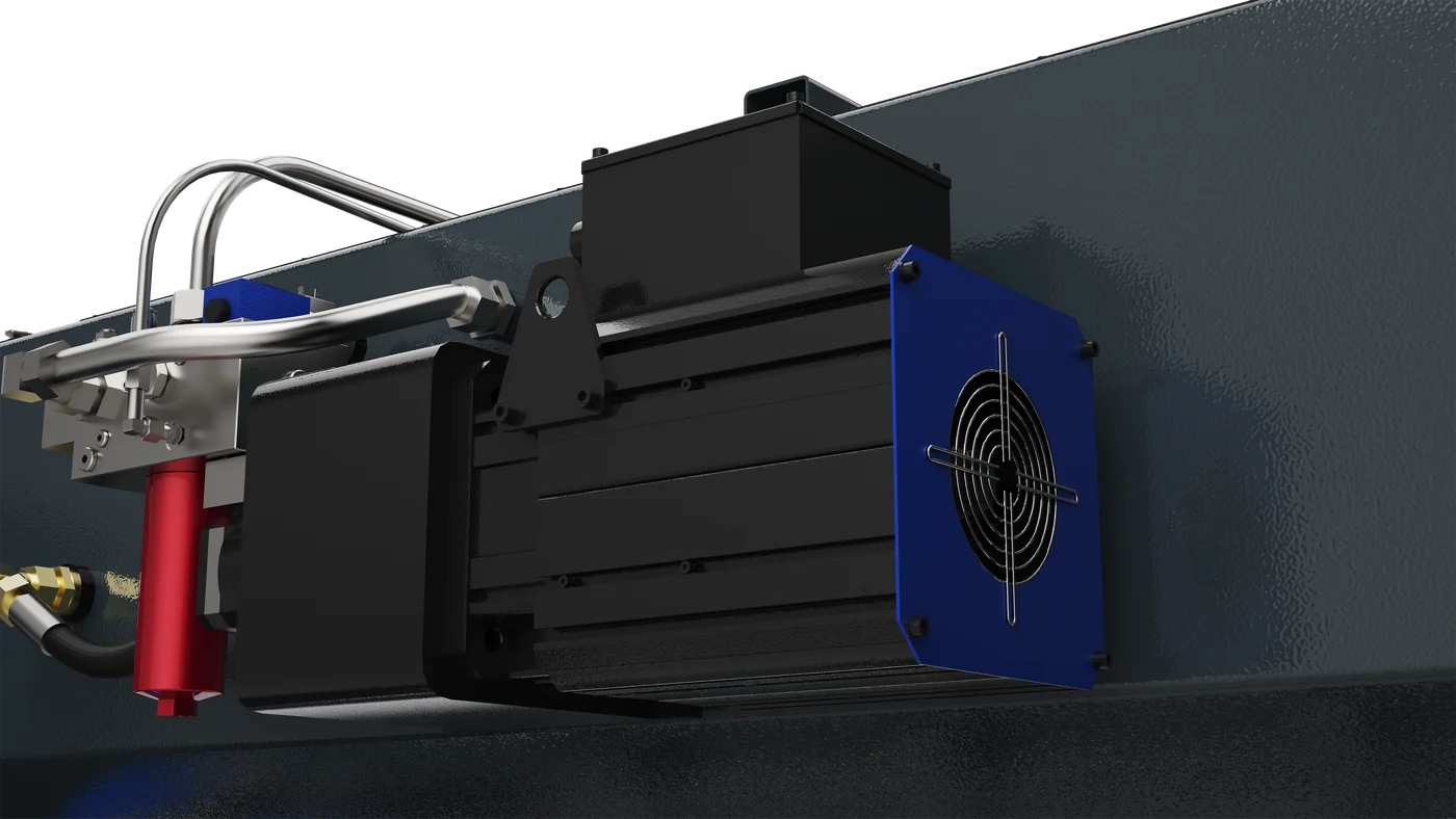
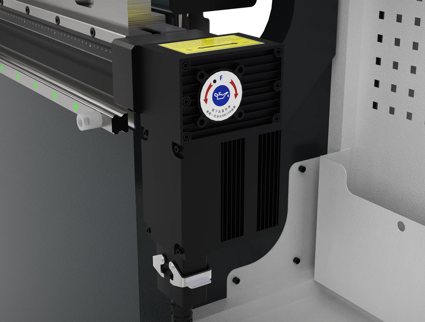
Servo-driven pump operation follows the bending cycle, supporting responsive hydraulic delivery and reduced motor operation during idle periods.
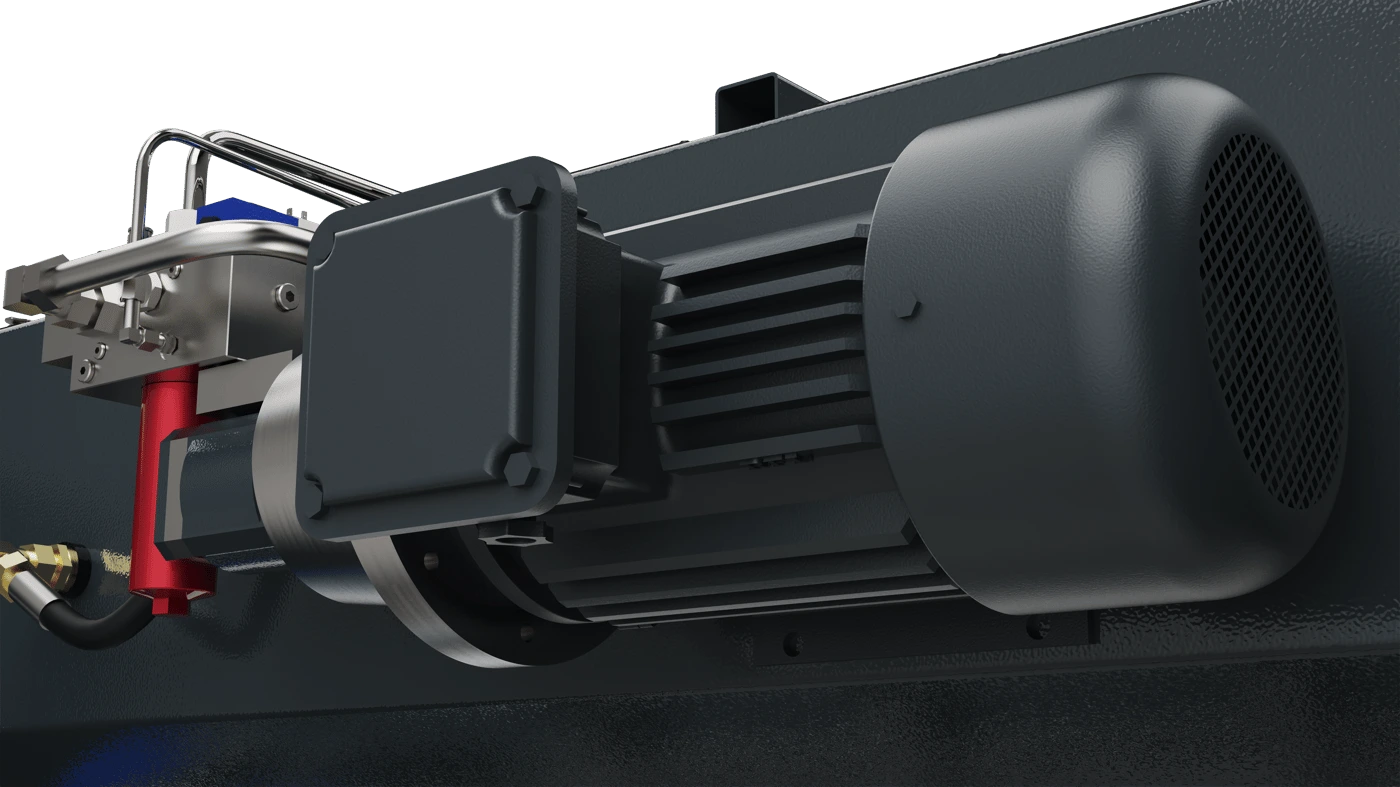
A conventional AC motor drives the hydraulic pump, providing a familiar power configuration for everyday bending and straightforward maintenance.
Motor configuration depends on the drive platform and application. Use the catalogue rating for the selected model.
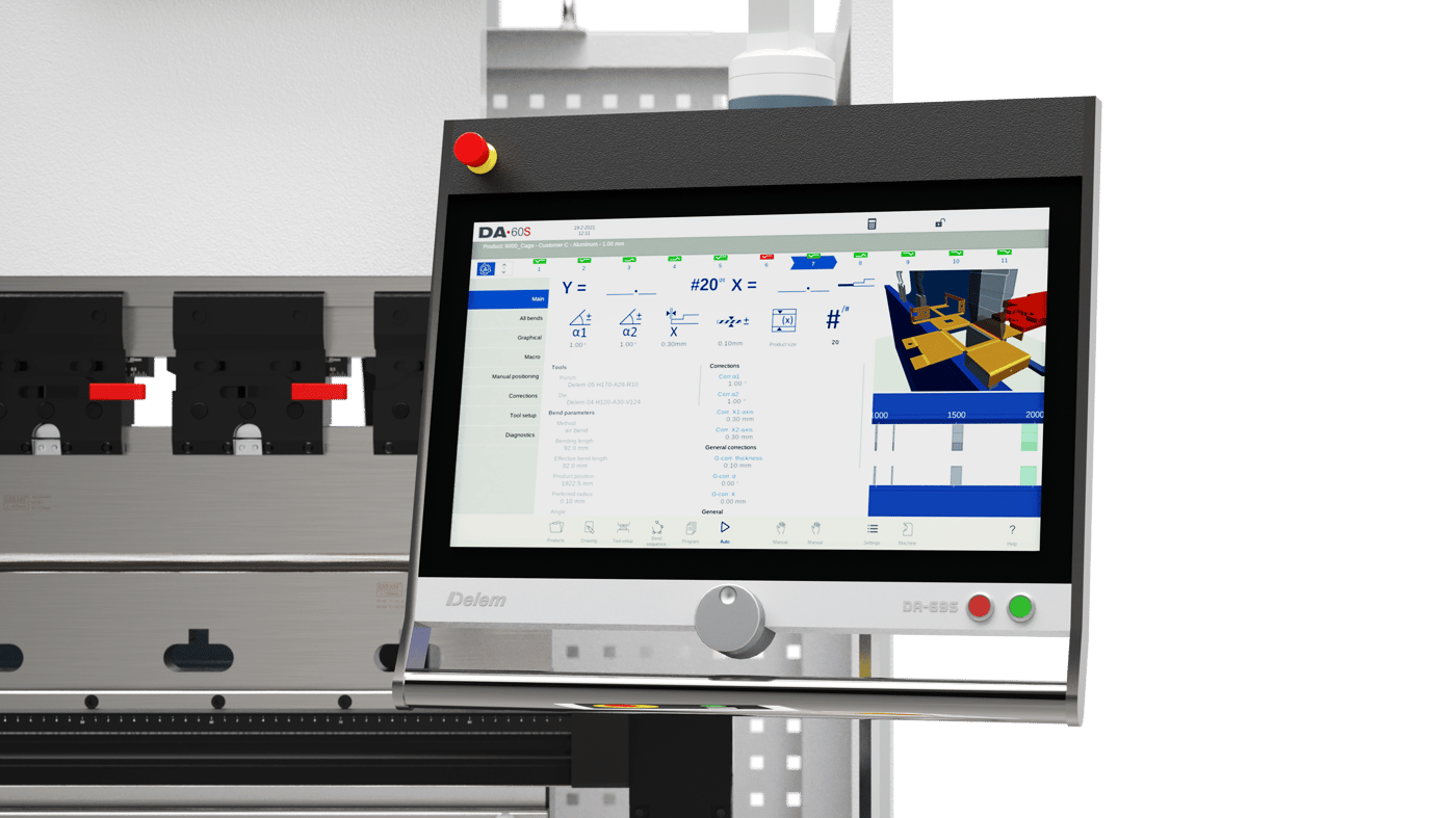
2D and 3D graphical programming brings part preparation, bend sequencing and production into a single touch interface.
UltraBend control package. Manufacturer control information.
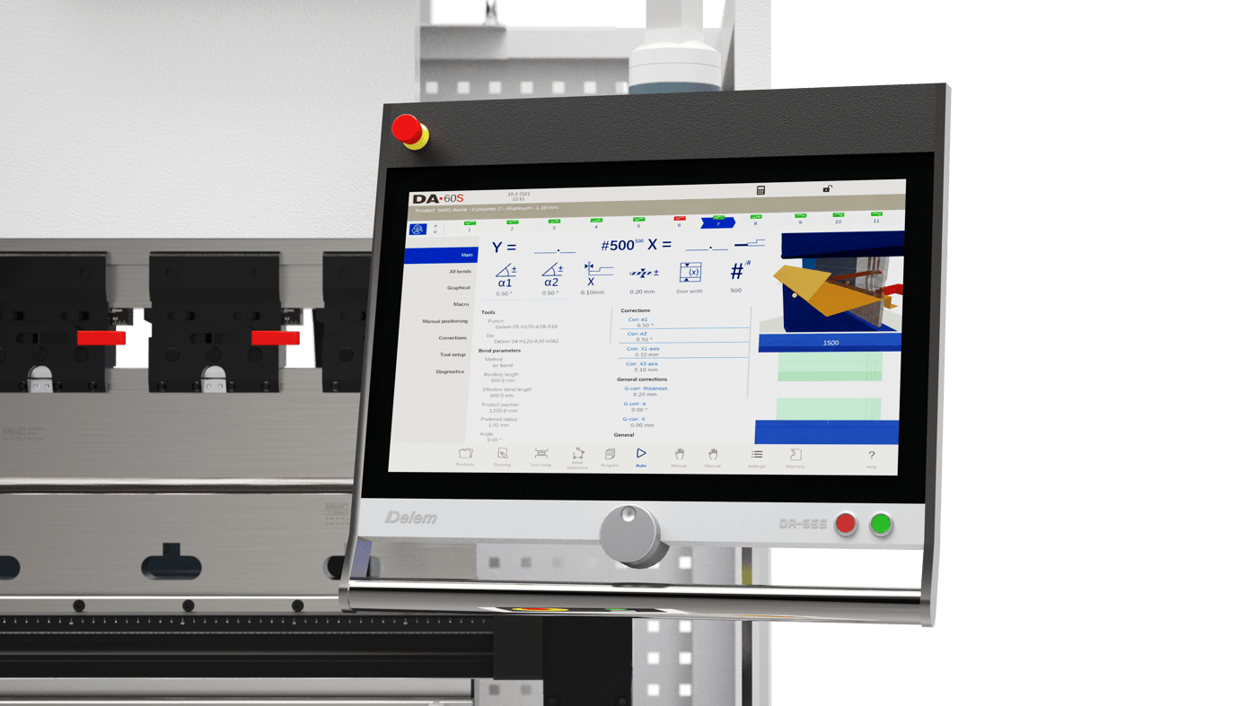
2D graphical programming combines automatic bend sequencing with a 3D view of the machine and tooling setup.
UltraBend control package. Manufacturer control information.
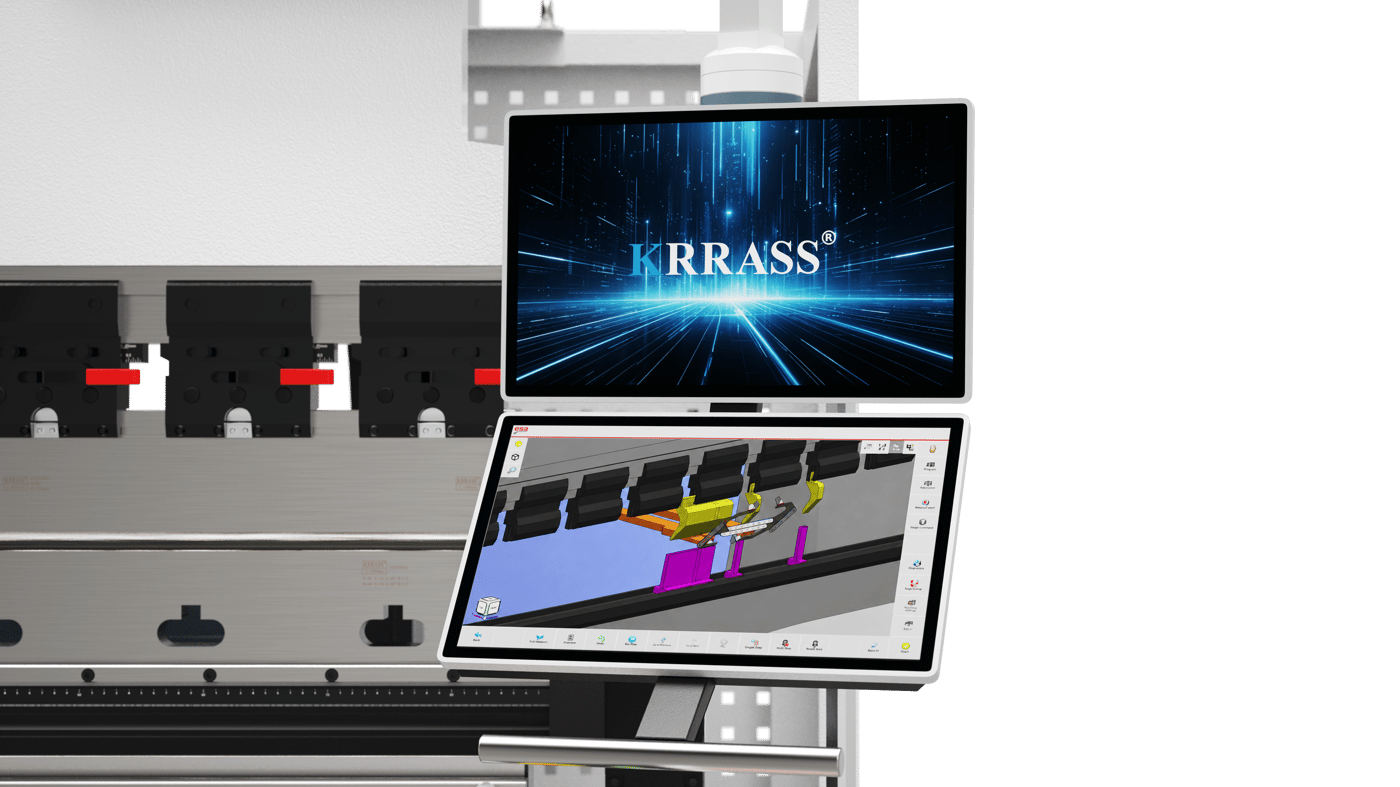
The S875 family provides a multi-touch interface and 3D CNC capabilities for graphical bending preparation and operation.
UltraBend control package. Manufacturer control information.
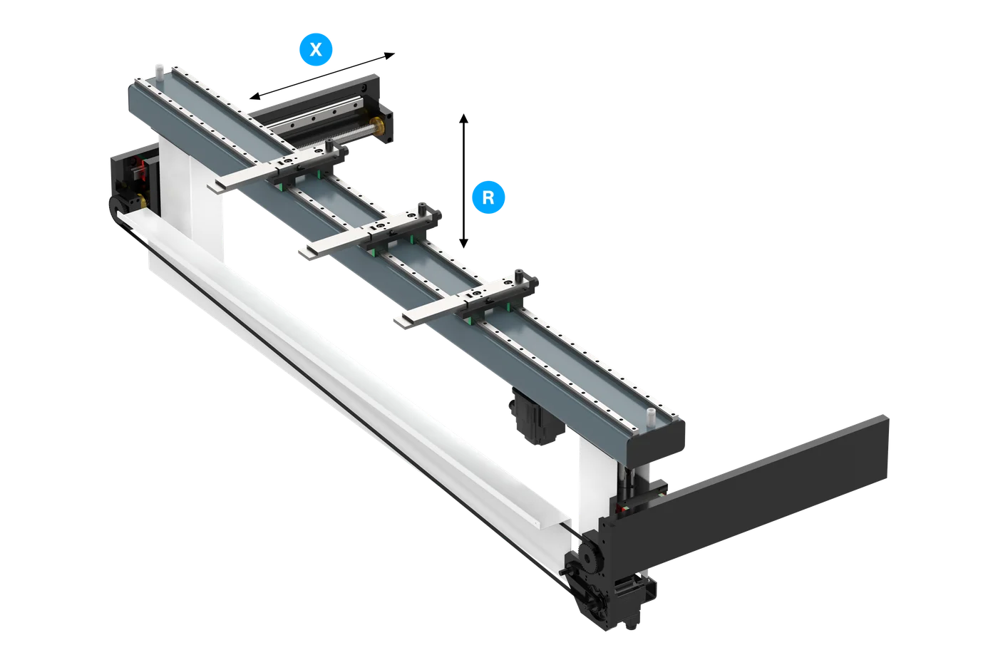
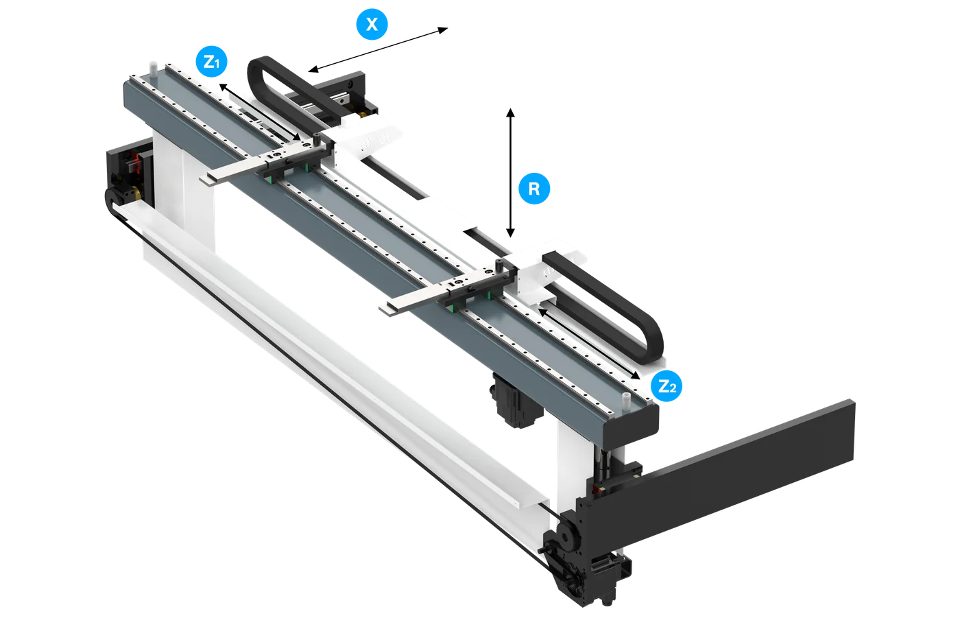
Set the bend depth and finger height for everyday positioning. Ball screws and linear guides support controlled movement.
Catalogue standard X/R backgauge. PDF printed pages 07–08. Backgauge axes are counted separately from the ram and crowning axes.
Position the stop fingers along the beam as well as in depth and height. A flexible arrangement for varied sheet widths and part geometry.
Optional four-axis backgauge. PDF printed page 16. Backgauge axes are counted separately from the ram and crowning axes.
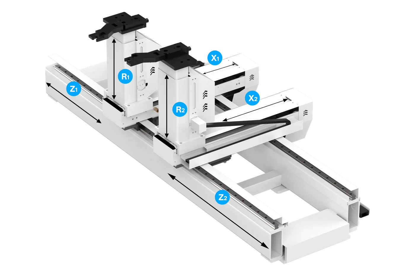
X1, X2, R1, R2, Z1 and Z2 independently position the fingers for more involved workpiece geometries.
Optional six-axis backgauge. PDF printed page 16. Backgauge axes are counted separately from the ram and crowning axes.
Choose a safety option for your working area. Both packages are optional and integrated with the machine's complete guarding arrangement.
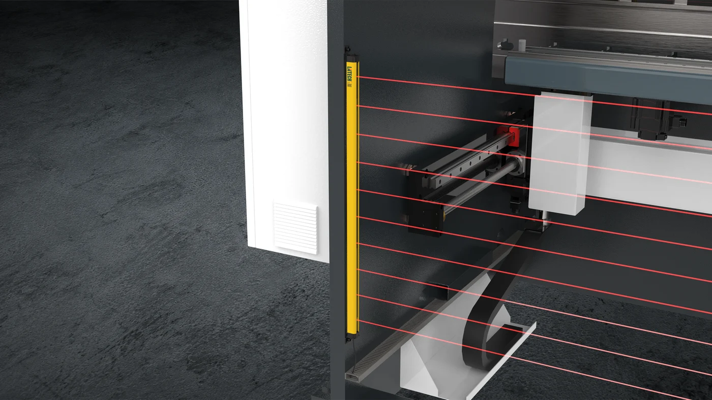
Optional
An infrared detection field monitors access to the protected area. The location and safety integration follow the machine's confirmed guarding arrangement.
Discuss this option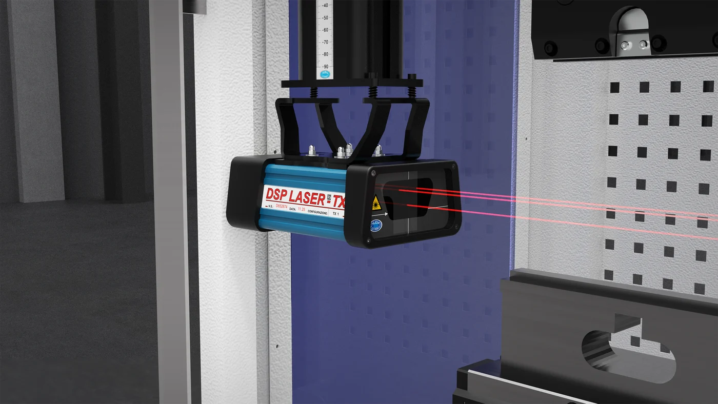
Optional
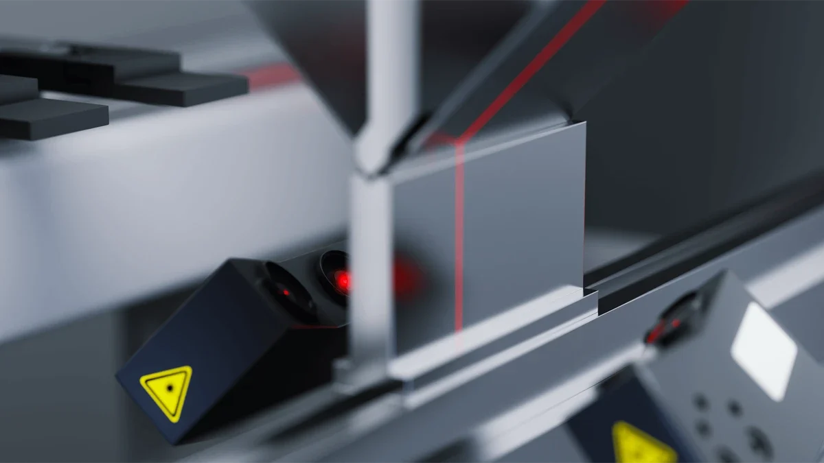
A DSP laser device monitors the area close to the tooling. Its mounting and control integration are specified as part of the machine's safeguarding package.
Discuss this optionCNC mechanical crowning adjusts the worktable to compensate for deflection across the working length.
Explore machine configurationSheet handling, angle measurement, tool changes and positioning. All four packages are optional, selected for your machine and application.
Optional
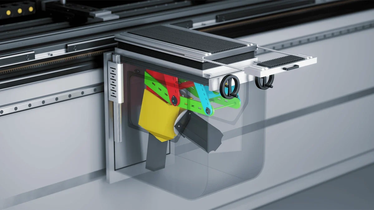
Unlike manually positioned front supports, a follower support tracks the workpiece as it turns during a bend. The CNC system calculates and controls the following angle and speed.
Discuss this optionOptional
Laser angle measurement provides information about the workpiece bend angle. It is a process-measurement option and serves a different purpose from the laser safety device.
Discuss this option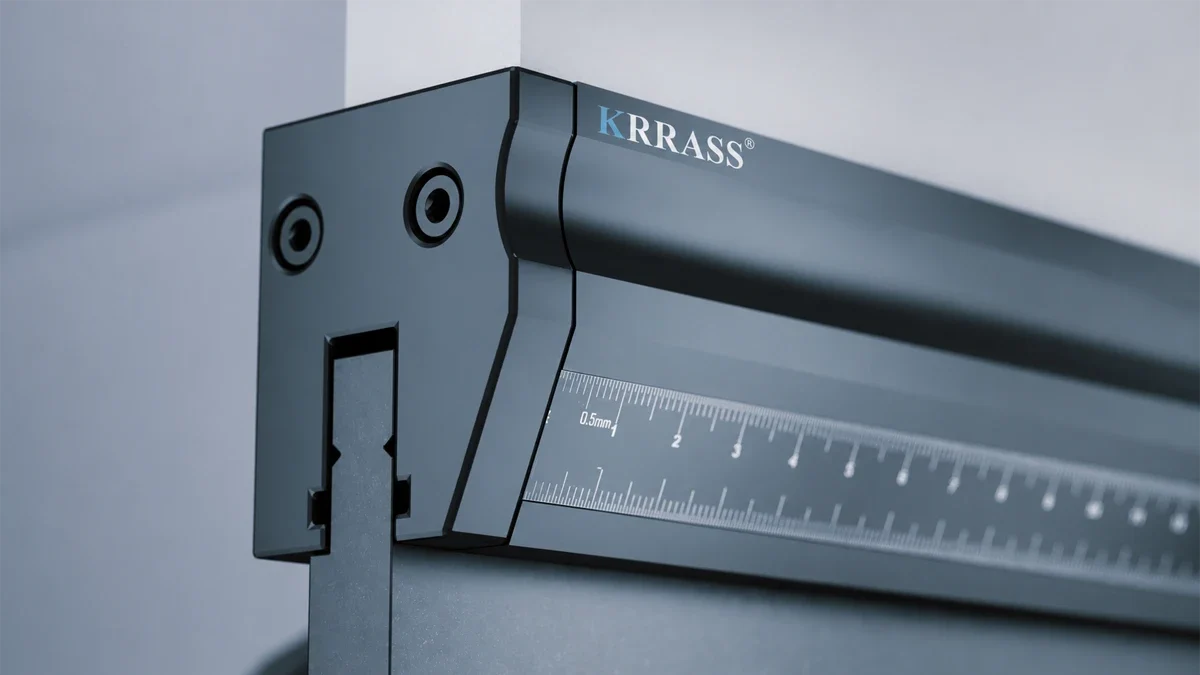
Optional
The WILA upper-tool system uses hydraulic clamping with electrically controlled clamping and release. It is a tooling-interface option for tool changes, not the same assembly as the catalogue quick clamp.
Discuss this option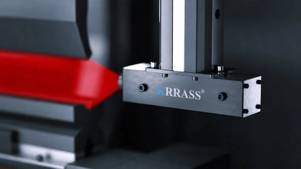
Optional
A projected laser line provides a visible reference for positioning the sheet before bending.
Discuss this optionChoose the punch, die opening and clamping interface for the material and bend geometry. The SNSIE catalogue includes double-V and multi-V tooling arrangements, as well as optional WILA hydraulic holders.
Explore tooling diagrams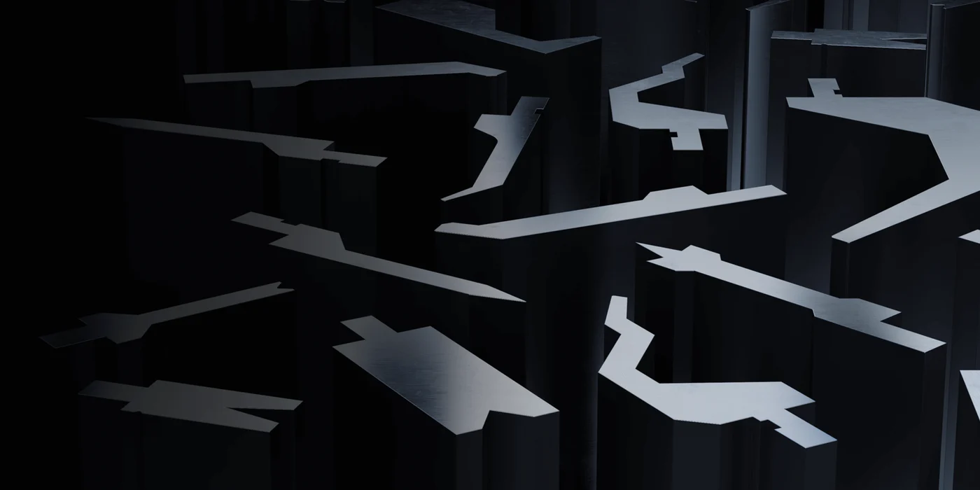
Component images illustrate configuration principles. Supplied components and brands follow the confirmed SNSIE machine package.
UltraBend control packages: Delem DA-69S, DA-66S or ESA S875. Frame dimensions follow the 2024 SNSIE catalogue; the selected control and axis package is specified in your quotation.
| Model | Pressure kN | Length mm | Upright distance mm | Throat depth mm | Cylinder stroke mm | Opening height mm | Die setting height mm | Main motor power kW | Oil tank volume L | Approaching speed mm/s | Working speed mm/s | Returning speed mm/s | Machine length mm | Machine width mm | Machine height mm | Weight kg | Details |
|---|---|---|---|---|---|---|---|---|---|---|---|---|---|---|---|---|---|
| SPES 40-1600 | 400 | 1,600 | 1,200 | 300 | 150 | 450 | 545 | 3.7 x 2 | 50 x 2 | 300 | 15 | 150 | 2,200 | 1,450 | 2,155 | 4,300 | |
| SPES 70-1600 | 700 | 1,600 | 1,200 | 350 | 170 | 460 | 555 | 3.7 x 2 | 50 x 2 | 300 | 15 | 150 | 2,200 | 1,450 | 2,155 | 4,500 | |
| SPES 70-2500 | 700 | 2,500 | 2,000 | 350 | 170 | 460 | 555 | 3.7 x 2 | 50 x 2 | 300 | 15 | 150 | 3,220 | 1,780 | 2,650 | 5,500 | |
| SPES 110-2500 | 1,100 | 2,500 | 2,000 | 400 | 200 | 490 | 585 | 5.5 x 2 | 70 x 2 | 280 | 13 | 150 | 3,240 | 1,780 | 2,680 | 7,000 | |
| SPES 110-3200 | 1,100 | 3,200 | 2,700 | 400 | 200 | 490 | 585 | 5.5 x 2 | 70 x 2 | 280 | 13 | 150 | 4,030 | 1,780 | 2,680 | 8,000 | |
| SPES 110-4100 | 1,100 | 4,100 | 3,300 | 400 | 200 | 490 | 585 | 5.5 x 2 | 70 x 2 | 280 | 13 | 150 | 4,830 | 1,780 | 2,780 | 10,000 | |
| SPES 130-3200 | 1,300 | 3,200 | 2,700 | 400 | 200 | 490 | 585 | 7.5 x 2 | 90 x 2 | 280 | 15 | 150 | 4,030 | 1,790 | 2,750 | 8,300 | |
| SPES 130-4100 | 1,300 | 4,100 | 2,700 | 400 | 200 | 490 | 585 | 7.5 x 2 | 90 x 2 | 280 | 15 | 150 | 4,830 | 1,790 | 2,850 | 11,300 | |
| SPES 130-5000 | 1,300 | 5,000 | 4,100 | 400 | 200 | 490 | 585 | 7.5 x 2 | 90 x 2 | 280 | 15 | 150 | 5,830 | 1,790 | 3,100 | 14,000 | |
| SPES 130-6000 | 1,300 | 6,000 | 4,800 | 400 | 200 | 490 | 585 | 7.5 x 2 | 90 x 2 | 280 | 15 | 150 | 6,830 | 1,790 | 3,200 | 16,000 | |
| SPES 170-3200 | 1,700 | 3,200 | 2,700 | 400 | 200 | 490 | 585 | 7.5 x 2 | 90 x 2 | 250 | 13 | 150 | 4,050 | 1,800 | 2,730 | 10,100 | |
| SPES 170-4100 | 1,700 | 4,100 | 3,400 | 400 | 200 | 490 | 585 | 7.5 x 2 | 90 x 2 | 250 | 13 | 150 | 4,700 | 1,800 | 2,830 | 12,100 | |
| SPES 170-5000 | 1,700 | 5,000 | 4,100 | 400 | 200 | 490 | 585 | 7.5 x 2 | 90 x 2 | 250 | 13 | 150 | 5,700 | 1,800 | 3,080 | 15,000 | |
| SPES 170-6000 | 1,700 | 6,000 | 5,000 | 400 | 200 | 490 | 585 | 7.5 x 2 | 90 x 2 | 250 | 13 | 150 | 6,700 | 1,800 | 3,180 | 18,000 | |
| SPES 220-3200 | 2,200 | 3,200 | 2,700 | 400 | 200 | 490 | 585 | 8.5 x 2 | 150 x 2 | 200 | 13 | 150 | 4,020 | 1,850 | 2,850 | 12,000 | |
| SPES 220-4100 | 2,200 | 4,100 | 3,300 | 400 | 200 | 490 | 585 | 8.5 x 2 | 150 x 2 | 200 | 13 | 150 | 4,820 | 1,850 | 3,100 | 13,900 | |
| SPES 220-5000 | 2,200 | 5,000 | 4,100 | 400 | 200 | 490 | 585 | 8.5 x 2 | 150 x 2 | 200 | 13 | 150 | 5,820 | 1,850 | 3,250 | 18,200 | |
| SPES 220-6000 | 2,200 | 6,000 | 5,000 | 400 | 200 | 490 | 585 | 8.5 x 2 | 150 x 2 | 200 | 13 | 150 | 6,820 | 1,850 | 3,350 | 21,000 | |
| SPES 250-3200 | 2,500 | 3,200 | 2,700 | 450 | 250 | 540 | 635 | 13 x 2 | 200 x 2 | 160 | 15 | 140 | 4,050 | 1,860 | 3,000 | 14,000 | |
| SPES 250-4100 | 2,500 | 4,100 | 3,300 | 450 | 250 | 540 | 635 | 13 x 2 | 200 x 2 | 160 | 15 | 140 | 4,850 | 1,860 | 3,100 | 16,000 | |
| SPES 250-5000 | 2,500 | 5,000 | 3,800 | 450 | 250 | 540 | 635 | 13 x 2 | 200 x 2 | 160 | 15 | 140 | 5,850 | 1,860 | 3,250 | 21,000 | |
| SPES 250-6000 | 2,500 | 6,000 | 5,000 | 450 | 250 | 520 | 615 | 13 x 2 | 200 x 2 | 160 | 15 | 140 | 6,850 | 1,860 | 3,350 | 24,000 | |
| SPES 300-3200 | 3,000 | 3,200 | 2,700 | 450 | 250 | 520 | 615 | 13 x 2 | 200 x 2 | 160 | 13 | 140 | 4,600 | 2,260 | 3,400 | 17,700 | |
| SPES 300-4100 | 3,000 | 4,100 | 3,300 | 450 | 250 | 520 | 615 | 13 x 2 | 200 x 2 | 160 | 13 | 140 | 5,400 | 2,260 | 3,500 | 20,300 | |
| SPES 300-5000 | 3,000 | 5,000 | 3,800 | 500 | 250 | 520 | 615 | 13 x 2 | 200 x 2 | 160 | 13 | 140 | 6,430 | 2,260 | 3,680 | 26,100 | |
| SPES 300-6000 | 3,000 | 6,000 | 5,000 | 500 | 250 | 520 | 615 | 13 x 2 | 200 x 2 | 160 | 13 | 140 | 7,430 | 2,260 | 3,850 | 30,400 |
No catalogue models meet both requirements. Lower the filters or discuss a custom configuration with SNSIE.
Printed page 13 · View the original PDF · Motor power and oil volumes refer to two units.
| Model | Pressure kN | Length mm | Upright distance mm | Throat depth mm | Cylinder stroke mm | Opening height mm | Die setting height mm | Main motor power kW | Oil tank volume L | Approaching speed mm/s | Working speed mm/s | Returning speed mm/s | Machine length mm | Machine width mm | Machine height mm | Weight kg | Details |
|---|---|---|---|---|---|---|---|---|---|---|---|---|---|---|---|---|---|
| SPS 40-1600 | 400 | 1,600 | 1,200 | 300 | 150 | 450 | 545 | 5.5 | 160 | 230 | 0-15 | 140 | 2,200 | 1,450 | 2,155 | 4,300 | |
| SPS 70-1600 | 700 | 1,600 | 1,200 | 350 | 170 | 460 | 555 | 7.5 | 160 | 230 | 0-15 | 140 | 2,200 | 1,450 | 2,155 | 4,500 | |
| SPS 70-2500 | 700 | 2,500 | 2,000 | 350 | 170 | 460 | 555 | 7.5 | 225 | 230 | 0-15 | 140 | 3,220 | 1,780 | 2,650 | 5,500 | |
| SPS 110-2500 | 1,100 | 2,500 | 2,000 | 400 | 200 | 490 | 585 | 11 | 225 | 220 | 0-15 | 140 | 3,240 | 1,780 | 2,680 | 7,000 | |
| SPS 110-3200 | 1,100 | 3,200 | 2,700 | 400 | 200 | 490 | 585 | 11 | 350 | 220 | 0-15 | 140 | 4,030 | 1,780 | 2,680 | 8,000 | |
| SPS 110-4100 | 1,100 | 4,100 | 3,300 | 400 | 200 | 490 | 585 | 11 | 350 | 220 | 0-15 | 140 | 4,830 | 1,780 | 2,780 | 10,000 | |
| SPS 130-3200 | 1,300 | 3,200 | 2,700 | 400 | 200 | 490 | 585 | 11 | 350 | 200 | 0-15 | 140 | 4,030 | 1,790 | 2,750 | 8,300 | |
| SPS 130-4100 | 1,300 | 4,100 | 2,700 | 400 | 200 | 490 | 585 | 11 | 430 | 200 | 0-15 | 140 | 4,830 | 1,790 | 2,850 | 11,300 | |
| SPS 130-5000 | 1,300 | 5,000 | 4,100 | 400 | 200 | 490 | 585 | 11 | 550 | 180 | 0-15 | 90 | 5,830 | 1,790 | 3,100 | 14,000 | |
| SPS 130-6000 | 1,300 | 6,000 | 4,800 | 400 | 200 | 490 | 585 | 11 | 550 | 180 | 0-15 | 90 | 6,830 | 1,790 | 3,200 | 16,000 | |
| SPS 170-3200 | 1,700 | 3,200 | 2,700 | 400 | 200 | 490 | 585 | 15 | 350 | 200 | 0-15 | 140 | 4,050 | 1,800 | 2,730 | 10,100 | |
| SPS 170-4100 | 1,700 | 4,100 | 3,400 | 400 | 200 | 490 | 585 | 15 | 430 | 200 | 0-15 | 140 | 4,700 | 1,800 | 2,830 | 12,100 | |
| SPS 170-5000 | 1,700 | 5,000 | 4,100 | 400 | 200 | 490 | 585 | 18.5 | 550 | 160 | 0-15 | 90 | 5,700 | 1,800 | 3,080 | 15,000 | |
| SPS 170-6000 | 1,700 | 6,000 | 5,000 | 400 | 200 | 490 | 585 | 18.5 | 550 | 160 | 0-15 | 90 | 6,700 | 1,800 | 3,180 | 18,000 | |
| SPS 220-3200 | 2,200 | 3,200 | 2,700 | 400 | 200 | 490 | 585 | 18.5 | 350 | 160 | 0-13 | 140 | 4,020 | 1,850 | 2,850 | 12,000 | |
| SPS 220-4100 | 2,200 | 4,100 | 3,300 | 400 | 200 | 490 | 585 | 18.5 | 430 | 160 | 0-13 | 140 | 4,820 | 1,850 | 3,100 | 13,900 | |
| SPS 220-5000 | 2,200 | 5,000 | 4,100 | 400 | 200 | 490 | 585 | 22.5 | 550 | 130 | 0-13 | 90 | 5,820 | 1,850 | 3,250 | 18,200 | |
| SPS 220-6000 | 2,200 | 6,000 | 5,000 | 400 | 200 | 490 | 585 | 22.5 | 550 | 130 | 0-13 | 90 | 6,820 | 1,850 | 3,350 | 21,000 | |
| SPS 250-3200 | 2,500 | 3,200 | 2,700 | 450 | 250 | 540 | 635 | 22.5 | 350 | 130 | 0-13 | 110 | 4,050 | 1,860 | 3,000 | 14,000 | |
| SPS 250-4100 | 2,500 | 4,100 | 3,300 | 450 | 250 | 540 | 635 | 22.5 | 430 | 130 | 0-13 | 110 | 4,850 | 1,860 | 3,100 | 16,000 | |
| SPS 250-5000 | 2,500 | 5,000 | 3,800 | 450 | 250 | 540 | 635 | 22.5 | 550 | 120 | 0-13 | 80 | 5,850 | 1,860 | 3,250 | 21,000 | |
| SPS 250-6000 | 2,500 | 6,000 | 5,000 | 450 | 250 | 520 | 615 | 22.5 | 550 | 120 | 0-13 | 80 | 6,850 | 1,860 | 3,350 | 24,000 | |
| SPS 300-3200 | 3,000 | 3,200 | 2,700 | 450 | 250 | 520 | 615 | 24.5 | 460 | 100 | 0-13 | 90 | 4,600 | 2,260 | 3,400 | 17,700 | |
| SPS 300-4100 | 3,000 | 4,100 | 3,300 | 450 | 250 | 520 | 615 | 24.5 | 460 | 100 | 0-13 | 90 | 5,400 | 2,260 | 3,500 | 20,300 | |
| SPS 300-5000 | 3,000 | 5,000 | 3,800 | 500 | 250 | 520 | 615 | 24.5 | 550 | 90 | 0-13 | 90 | 6,430 | 2,260 | 3,680 | 26,100 | |
| SPS 300-6000 | 3,000 | 6,000 | 5,000 | 500 | 250 | 520 | 615 | 24.5 | 550 | 90 | 0-13 | 90 | 7,430 | 2,260 | 3,850 | 30,400 |
No catalogue models meet both requirements. Lower the filters or discuss a custom configuration with SNSIE.
Printed page 14 · View the original PDF
| Model | Pressure kN | Length mm | Upright distance mm | Throat depth mm | Cylinder stroke mm | Opening height mm | Die setting height mm | Main motor power kW | Oil tank volume L | Approaching speed mm/s | Working speed mm/s | Returning speed mm/s | Machine length mm | Machine width mm | Machine height mm | Weight kg | Details |
|---|---|---|---|---|---|---|---|---|---|---|---|---|---|---|---|---|---|
| SPC 40-1600 | 400 | 1,600 | 1,200 | 300 | 150 | 450 | 545 | 5.5 | 160 | 230 | 0-15 | 140 | 2,200 | 1,450 | 2,155 | 4,300 | |
| SPC 70-1600 | 700 | 1,600 | 1,200 | 350 | 170 | 460 | 555 | 7.5 | 160 | 230 | 0-15 | 140 | 2,200 | 1,450 | 2,155 | 4,500 | |
| SPC 70-2500 | 700 | 2,500 | 2,000 | 350 | 170 | 460 | 555 | 7.5 | 225 | 230 | 0-15 | 140 | 3,220 | 1,780 | 2,650 | 5,500 | |
| SPC 110-2500 | 1,100 | 2,500 | 2,000 | 400 | 200 | 490 | 585 | 11 | 225 | 220 | 0-15 | 140 | 3,240 | 1,780 | 2,680 | 7,000 | |
| SPC 110-3200 | 1,100 | 3,200 | 2,700 | 400 | 200 | 490 | 585 | 11 | 350 | 220 | 0-15 | 140 | 4,030 | 1,780 | 2,680 | 8,000 | |
| SPC 110-4100 | 1,100 | 4,100 | 3,300 | 400 | 200 | 490 | 585 | 11 | 350 | 220 | 0-15 | 140 | 4,830 | 1,780 | 2,780 | 10,000 | |
| SPC 130-3200 | 1,300 | 3,200 | 2,700 | 400 | 200 | 490 | 585 | 11 | 350 | 200 | 0-15 | 140 | 4,030 | 1,790 | 2,750 | 8,300 | |
| SPC 130-4100 | 1,300 | 4,100 | 2,700 | 400 | 200 | 490 | 585 | 11 | 430 | 200 | 0-15 | 140 | 4,830 | 1,790 | 2,850 | 11,300 | |
| SPC 130-5000 | 1,300 | 5,000 | 4,100 | 400 | 200 | 490 | 585 | 11 | 550 | 180 | 0-15 | 90 | 5,830 | 1,790 | 3,100 | 14,000 | |
| SPC 130-6000 | 1,300 | 6,000 | 4,800 | 400 | 200 | 490 | 585 | 11 | 550 | 180 | 0-15 | 90 | 6,830 | 1,790 | 3,200 | 16,000 | |
| SPC 170-3200 | 1,700 | 3,200 | 2,700 | 400 | 200 | 490 | 585 | 15 | 350 | 200 | 0-15 | 140 | 4,050 | 1,800 | 2,730 | 10,100 | |
| SPC 170-4100 | 1,700 | 4,100 | 3,400 | 400 | 200 | 490 | 585 | 15 | 430 | 200 | 0-15 | 140 | 4,700 | 1,800 | 2,830 | 12,100 | |
| SPC 170-5000 | 1,700 | 5,000 | 4,100 | 400 | 200 | 490 | 585 | 15 | 550 | 160 | 0-15 | 90 | 5,700 | 1,800 | 3,080 | 15,000 | |
| SPC 170-6000 | 1,700 | 6,000 | 5,000 | 400 | 200 | 490 | 585 | 15 | 550 | 160 | 0-15 | 90 | 6,700 | 1,800 | 3,180 | 18,000 | |
| SPC 220-3200 | 2,200 | 3,200 | 2,700 | 400 | 200 | 490 | 585 | 18.5 | 350 | 160 | 0-13 | 140 | 4,020 | 1,850 | 2,850 | 12,000 | |
| SPC 220-4100 | 2,200 | 4,100 | 3,300 | 400 | 200 | 490 | 585 | 18.5 | 430 | 160 | 0-13 | 140 | 4,820 | 1,850 | 3,100 | 13,900 | |
| SPC 220-5000 | 2,200 | 5,000 | 4,100 | 400 | 200 | 490 | 585 | 18.5 | 550 | 130 | 0-13 | 90 | 5,820 | 1,850 | 3,250 | 18,200 | |
| SPC 220-6000 | 2,200 | 6,000 | 5,000 | 400 | 200 | 490 | 585 | 18.5 | 550 | 130 | 0-13 | 90 | 6,820 | 1,850 | 3,350 | 21,000 | |
| SPC 250-3200 | 2,500 | 3,200 | 2,700 | 450 | 250 | 540 | 635 | 18.5 | 350 | 130 | 0-13 | 110 | 4,050 | 1,860 | 3,000 | 14,000 | |
| SPC 250-4100 | 2,500 | 4,100 | 3,300 | 450 | 250 | 540 | 635 | 18.5 | 430 | 130 | 0-13 | 110 | 4,850 | 1,860 | 3,100 | 16,000 | |
| SPC 250-5000 | 2,500 | 5,000 | 3,800 | 450 | 250 | 540 | 635 | 18.5 | 550 | 120 | 0-13 | 80 | 5,850 | 1,860 | 3,250 | 21,000 | |
| SPC 250-6000 | 2,500 | 6,000 | 5,000 | 450 | 250 | 520 | 615 | 18.5 | 550 | 120 | 0-13 | 80 | 6,850 | 1,860 | 3,350 | 24,000 | |
| SPC 300-3200 | 3,000 | 3,200 | 2,700 | 450 | 250 | 520 | 615 | 22 | 460 | 100 | 0-13 | 90 | 4,600 | 2,260 | 3,400 | 17,700 | |
| SPC 300-4100 | 3,000 | 4,100 | 3,300 | 450 | 250 | 520 | 615 | 22 | 460 | 100 | 0-13 | 90 | 5,400 | 2,260 | 3,500 | 20,300 | |
| SPC 300-5000 | 3,000 | 5,000 | 3,800 | 500 | 250 | 520 | 615 | 22 | 550 | 90 | 0-13 | 90 | 6,430 | 2,260 | 3,680 | 26,100 | |
| SPC 300-6000 | 3,000 | 6,000 | 5,000 | 500 | 250 | 520 | 615 | 22 | 550 | 90 | 0-13 | 90 | 7,430 | 2,260 | 3,850 | 30,400 |
No catalogue models meet both requirements. Lower the filters or discuss a custom configuration with SNSIE.
Printed page 15 · View the original PDF
Estimate air-bending force using the SNSIE catalogue formula.
F = 65 × t² / V × bend length (m) × material factor. The result is in metric tonnes-force; 1 tf = 9.80665 kN.
View the force chartApproximation for air bending. Verify tooling capacity and material grade. This estimate does not establish a machine’s safe bending capacity.
Tell us about your material, part geometry and production needs.